SHERAZ ASGHAR
Technical Artist / Solutions Engineer
Filters All Categories
Sort by Newest first
Rapid City
PHOTOGRAPHY
Rapid City
Jun 25, 2026 Photography

A short June trip through the Black Hills of South Dakota, based out of Rapid City. Two carved mountains anchor it — Mount Rushmore, finished and famous, and Crazy Horse a few miles away, still being cut and decades from done. The rest is the drive: granite, pine, and a lot of open sky.

Four Cities and a Town
PHOTOGRAPHY
Four Cities and a Town
Aug 29, 2026 Photography

Four Cities and a Town follows a late-summer run north through Ireland and Scotland — Dublin, then Drogheda on the Boyne, across to Belfast, over the water to Glasgow, and east to Edinburgh. The collection leans on what the weather gave it: grey light on pale stone, wet pavement holding a reflection, and the short bright hours in…

Six Country, Nine City
PHOTOGRAPHY
Six Country, Nine City
Apr 20, 2026 Photography

Six Country Escape is a visual journey through six countries and nine cities, captured through architecture, street life, landscapes, food, and quiet everyday moments. Each photograph reflects the feeling of being there, from historic streets and colorful markets to peaceful courtyards, coastal views, and late-night city scenes. Shot…

WebGPU Automotive Configurator
UNITY
WebGPU Automotive Configurator
Feb 20, 2024 WebGPU

This project is a real-time WebGPU automotive visualization study built in Unity, focused on material customization, browser delivery, and optimized asset performance. The goal was to create an interactive vehicle experience where users could explore different material looks directly through the web. I used Maya to optimize and prepare…

A project about nothing
UNITY
A project about nothing
Aug 21, 2023 Animation

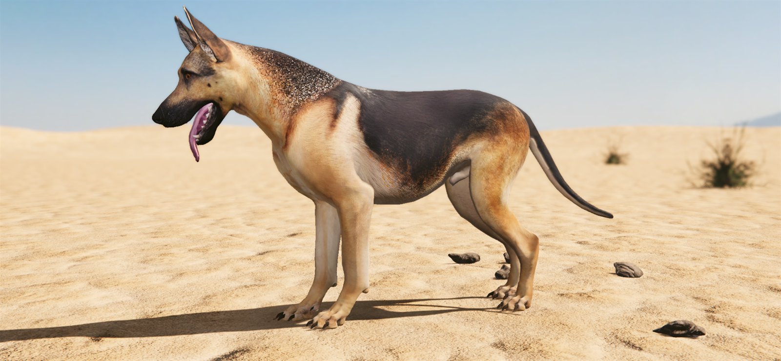
A Project About Nothing is a small real-time Unity study built around a field dog wandering through a desert environment. The goal was to examine the poses, movement, and interaction logic the dog might use while responding to a caretaker. The base dog model was purchased by Unity from TurboSquid and provided for this study. I reworked…

Minion Mayhem
CINEMA
Minion Mayhem
Jul 20, 2016 CG Animation

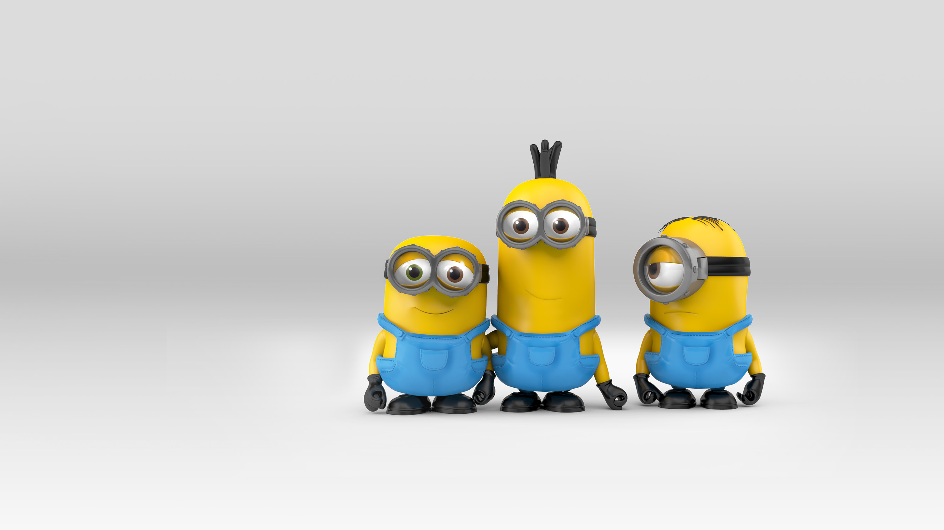
This project was a stylized CG animation created as part of a licensed Mega Bloks campaign featuring the Minions universe in collaboration with Mattel and Illumination. The goal was to take the familiar toy aesthetic and push it into a playful cinematic world, where everything feels like it’s built, broken, and rebuilt from actual…

TMNT 80s Blockfied
CINEMA
TMNT 80s Blockfied
Jan 10, 2017 CG Animation

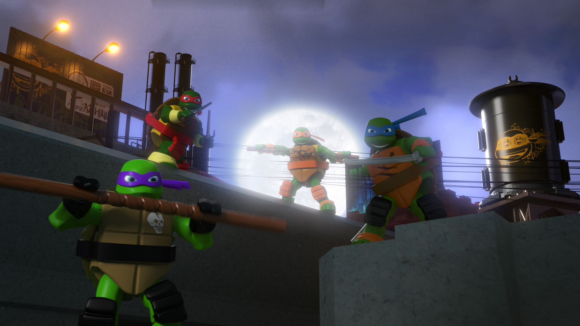
This project was a stylized CG animation inspired by the classic 80s Turtles theme intro, created using Mega Bloks toy-based characters and environments. The goal was to recreate the energy, attitude, and action of the original animated intro while translating it into a cinematic toy-style CG world. The project was developed as part of a…

SPARTAN MARK VI
CINEMA
SPARTAN MARK VI
Aug 20, 2014 CG Animation

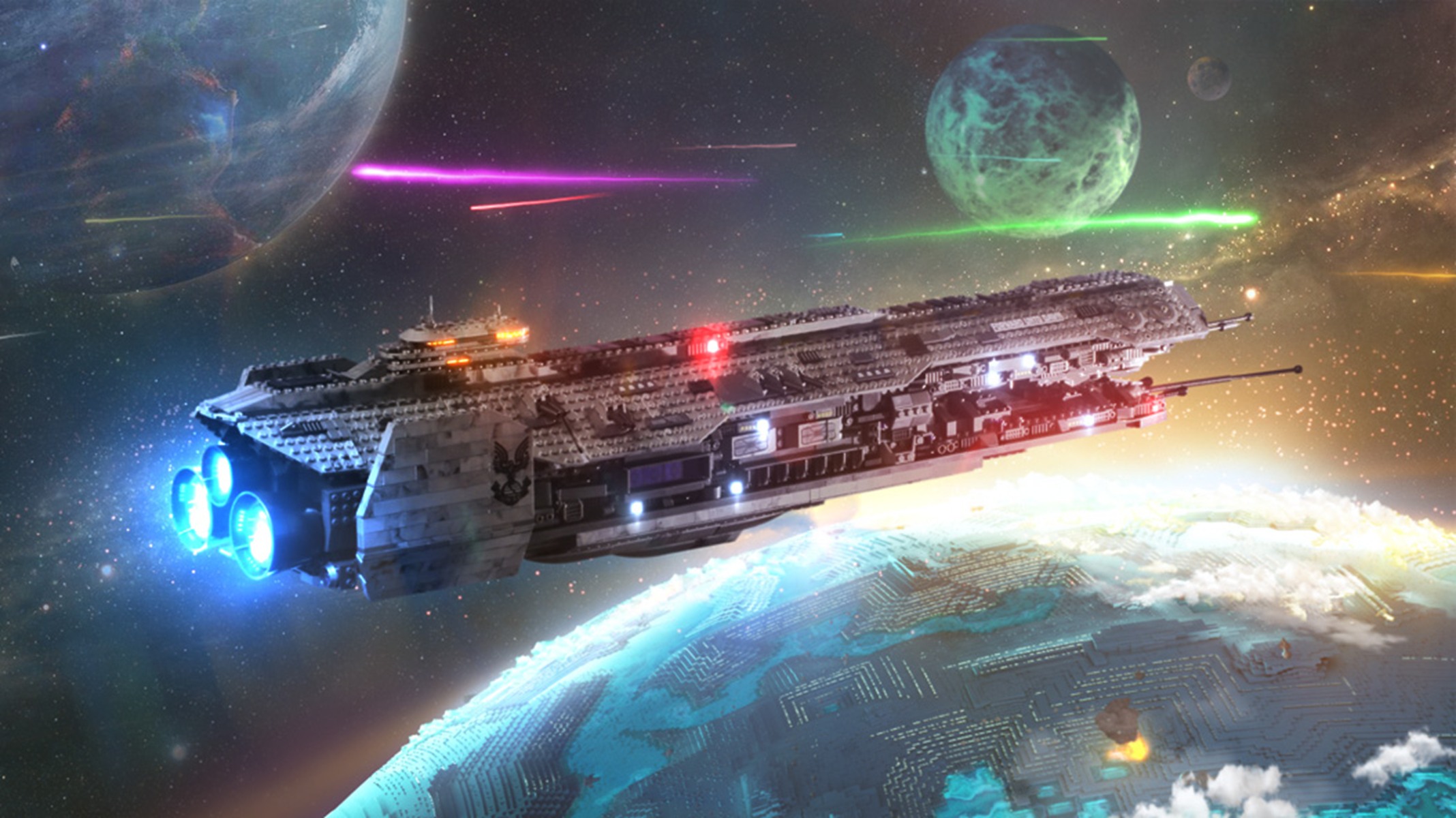
This project was a stylized CG animation created as part of a licensed Mega Bloks campaign featuring the Halo universe in collaboration with Mattel. The goal was to translate the dramatic tone and scale of Halo 4 into a toy-based cinematic language, where the forms remained true to the Mega Bloks aesthetic while the lighting, staging…

World of Warcraft
WEB
World of Warcraft
Jun 14, 2013 Web

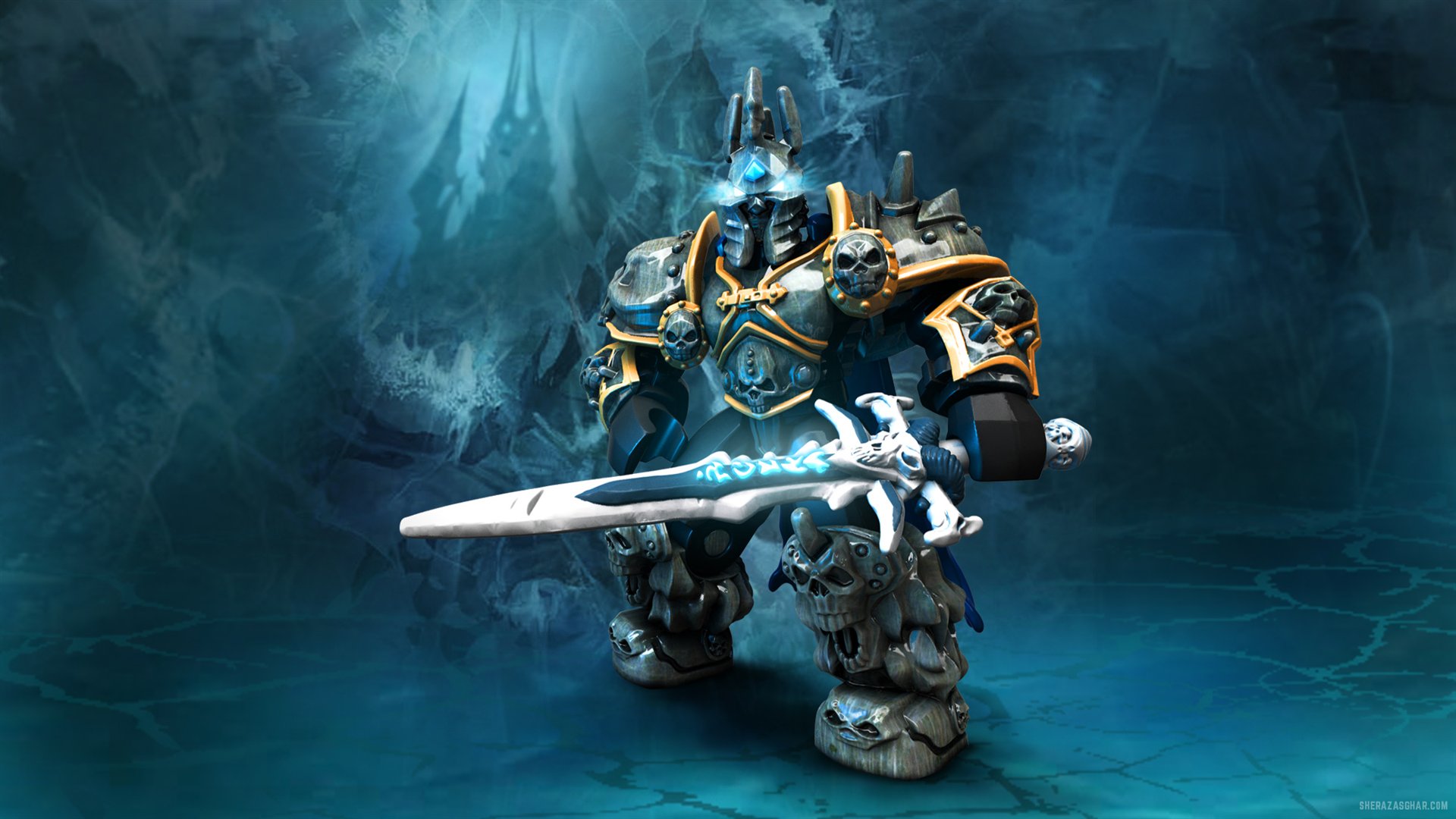
Created for Mega Bloks during their licensed partnership with Blizzard Entertainment, this interactive website brought the world of World of Warcraft into the Mega Bloks universe through a fully immersive digital experience. The goal was to create a web destination that captured the fantasy, scale, and storytelling of Azeroth while…

Destiny TVC
CINEMA
Destiny TVC
Jun 14, 2017 VFX

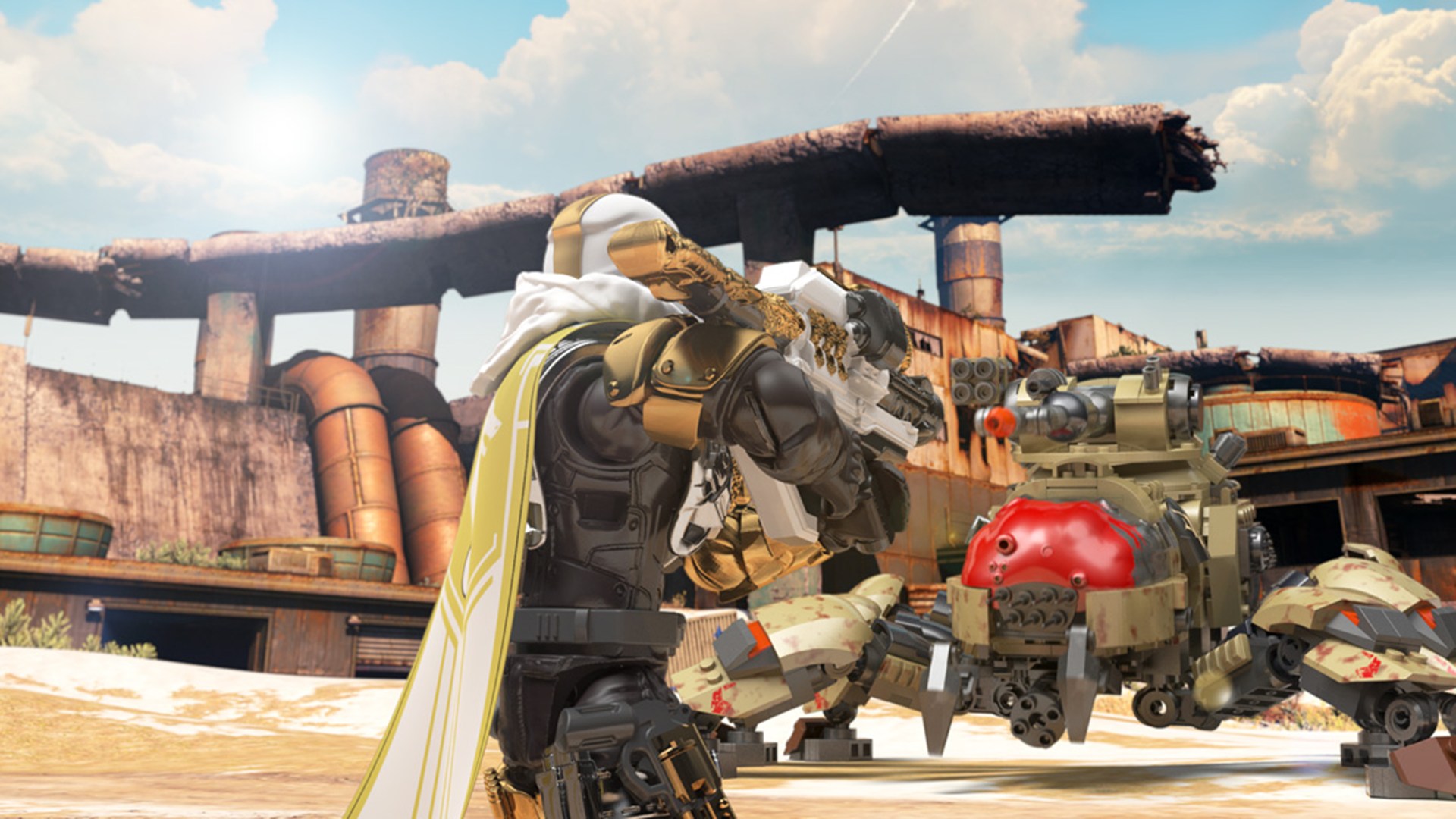
This project is a 7-second cinematic breakdown from a Destiny TVC sequence produced as part of an official Megabloks / Mattel Halo campaign. The animation was created by me directly for the TVC production, working from storyboard direction provided by Bungie and using manufacturing-ready character and vehicle assets supplied by the…

Halo FOD
CINEMA
Halo FOD
Jul 15, 2018 CG Animation

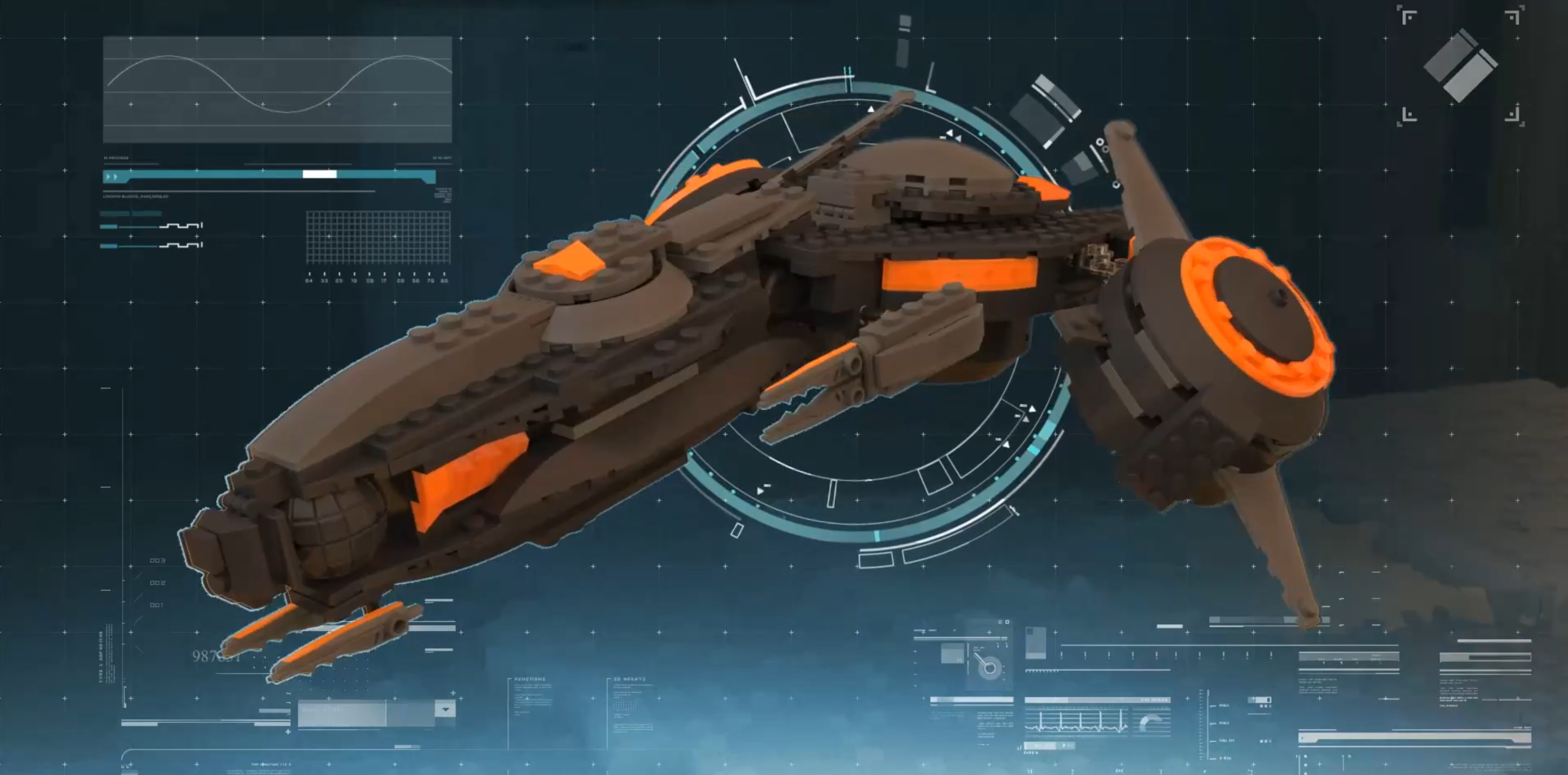
This piece began with something simple and physical, a Megabloks / Mattel Halo ship, animated through stop-motion frame by frame created by stop-motion animators at Mega Bloks / Mattel. It was never perfect. It jittered, it shifted, it breathed in a way digital animation often smooths away. But that imperfection became the soul of the…

Machine01
MACHINIST
Machine01
Dec 22, 2021 Machining

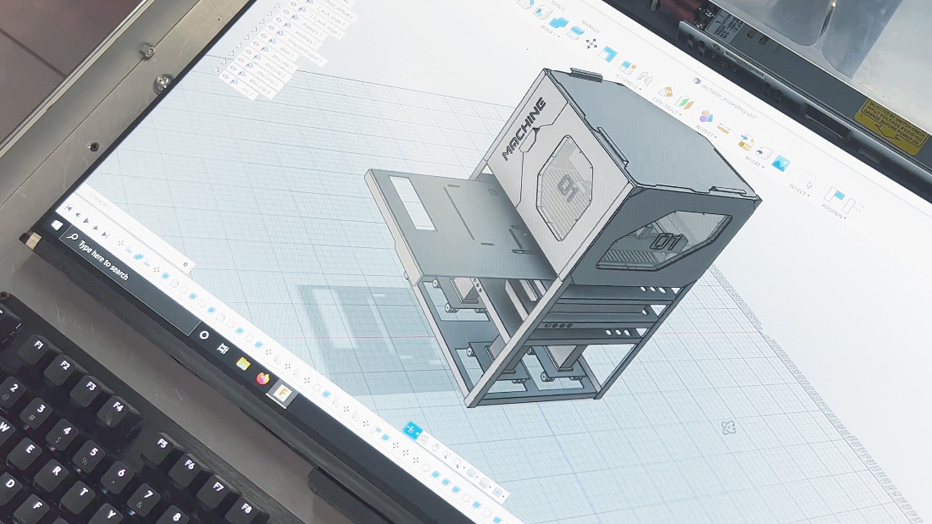
This is a personal project: a fully self-built CNC milling machine developed over the course of a year, designed and engineered from the ground up using Fusion 360 for mechanical design, structure, and system planning. The machine was custom-built rather than purchased as a kit, combining mechanical design, electronics integration, and…

Magnext TVC
CINEMA
Magnext TVC
Sep 21, 2017 CG Animation

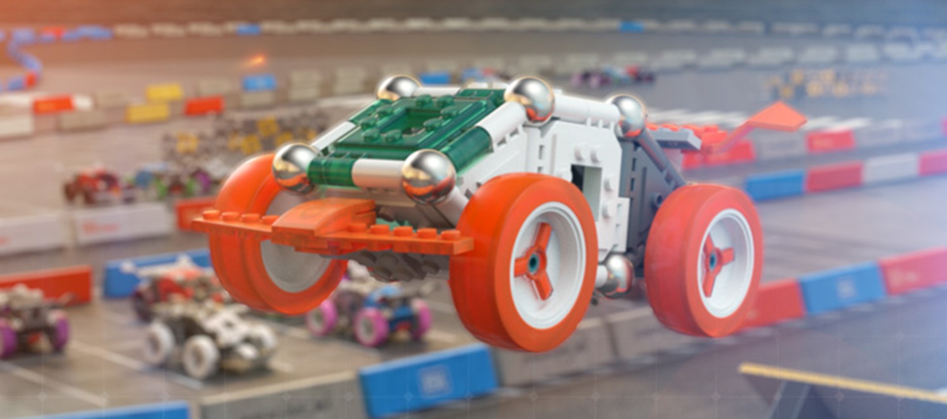
This project is a 10-second cinematic TVC created for MagneXt, a magnetic construction toy line developed by Mattel. The concept focuses on a single continuous shot that demonstrates how individual magnetic components assemble themselves into fully formed vehicles, transitioning seamlessly into high-speed action across race tracks…

Gumpaway
WEB
Gumpaway
Jun 11, 2016 Web

This project documents my journey biking across Canada, from the Pacific coast to the Atlantic Ocean, covering a total distance of approximately 6,321 km in just 42 days. Averaging between 150–250 km per day, the ride was an intense test of endurance, discipline, and mindset, driven by a personal goal to push physical limits while…

Halo Scorpion TVC
CINEMA
Halo Scorpion TVC
Mar 15, 2014 CG Animation

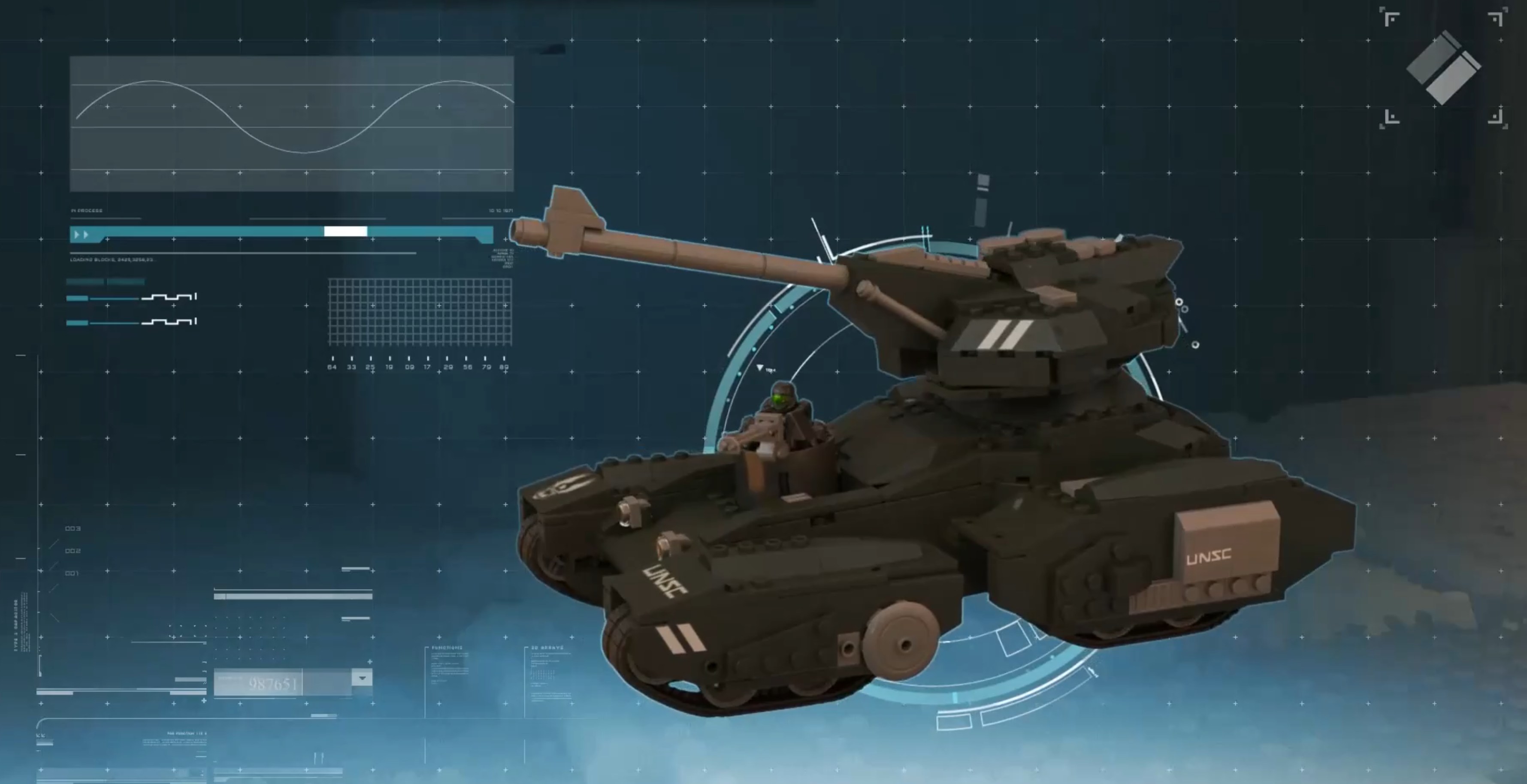
This project was created as a 10-second cinematic TV spot featuring the Halo Scorpion, a canon armored vehicle within the Halo universe reinterpreted through Megabloks / Mattel's physical toy design language. The sequence follows the same structured approach as the Pegasus spot, beginning with official Halo branding and transitioning…

Halo Pegasus TVC
CINEMA
Halo Pegasus TVC
Mar 15, 2014 CG Animation

This project was created as a 10-second cinematic TV spot featuring the Halo Pegasus, a canon vehicle within the Halo universe reinterpreted through Megabloks / Mattel's physical toy design language. The sequence begins with original Halo gameplay footage, grounding the viewer in the established universe before transitioning into a…

Turrentblok Mixed Reality
MIXED REALITY
Turrentblok Mixed Reality
Nov 11, 2015 AR

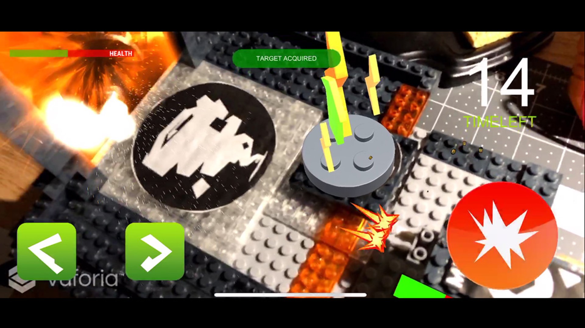
This project is a mixed reality gameplay prototype developed in Unity, combining physical computing with real-time augmented reality. The experience is built around a physical MEGA Bloks-based environment enhanced with AR tracking using Vuforia, where real-world markers dynamically control and trigger digital gameplay elements. Two…

Rover Mixed Reality
MIXED REALITY
Rover Mixed Reality
Aug 12, 2015 AR

This project is a mixed reality prototype built around a physical Mega Bloks / Mattel rover, combining real-world toy hardware with a Unity-based control and feedback system. I modified the rover with custom steering components, including LEGO parts, and integrated motors, servo steering, LEDs, a piezo buzzer, and Bluetooth communication…

Shapeshifters
UNITY
Shapeshifters
Jul 18, 2018 Robotics

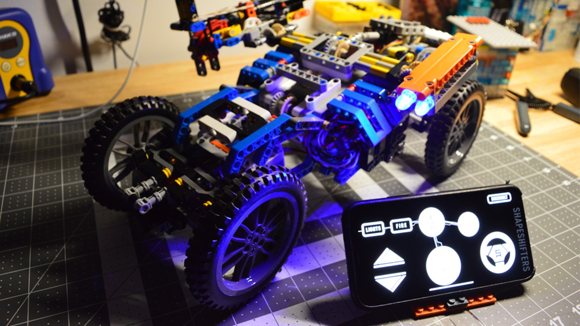
This project is a fully built modular RC-style vehicle system developed entirely using LEGO components, designed to explore physical computing, mechanical engineering, and real-time interactive control through Unity. The vehicle was engineered with functional steering and suspension systems built directly into the LEGO structure…

Roboblok
MICROCONTROLLERS
Roboblok
Jan 10, 2013 Electronics

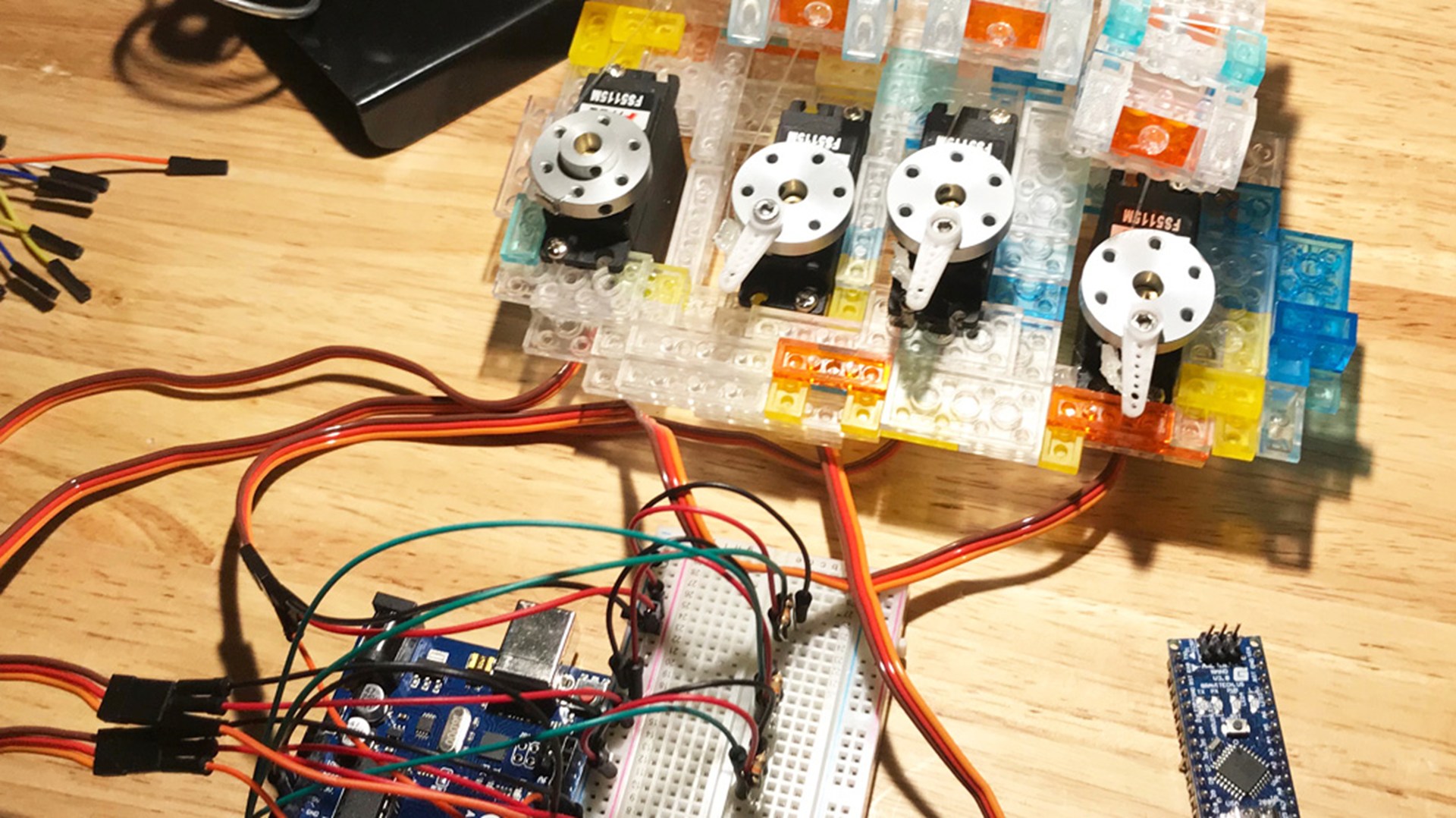
This project is a wearable robotic hand system built using Mega Bloks Micro components as the structural base, combined with embedded electronics and wireless control systems to create a gesture-driven interface. The robotic hand is actuated using five servos responsible for finger curling and movement, allowing the physical structure to…

Minion Tracking at Mattel
CINEMA
Minion Tracking at Mattel
Nov 14, 2016 Match-Move

This project explores motion tracking and visual effects integration using real-world footage combined with 3D animation and compositing techniques. The sequence was filmed using an iPhone 7 and used as a base plate for testing distant camera tracking and compositing workflows. The footage was tracked using Boujou to reconstruct accurate…

Minions at Cafe
CINEMA
Minions at Cafe
Jan 5, 2017 VFX

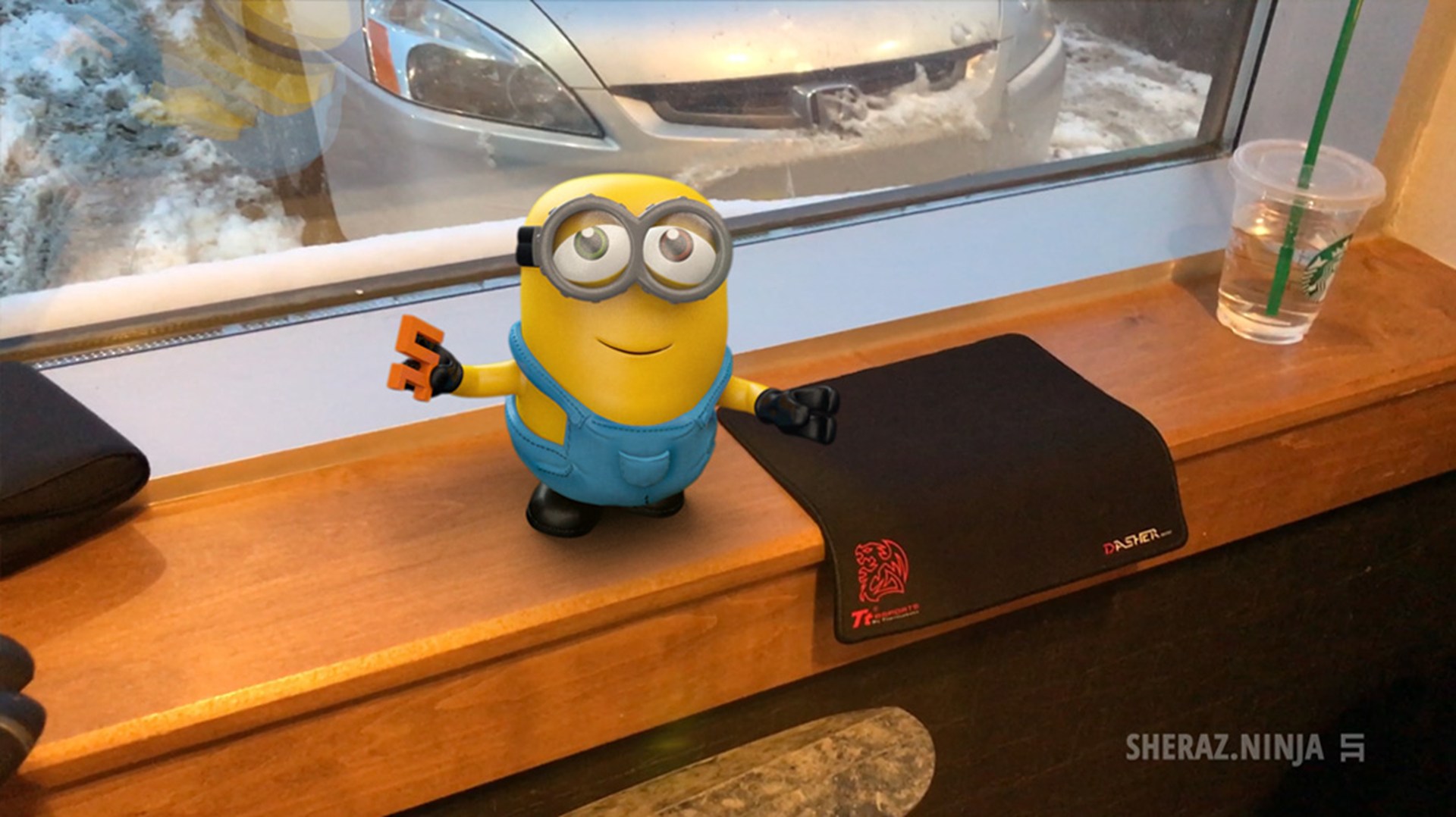
This project is a motion tracking and visual effects experiment set in a real-world cafe environment. The background footage was captured on location in Montreal, and used as a live-action plate for integrating CG character animation into a naturally filmed setting. The scene was tracked using Boujou to reconstruct accurate camera…

Neoshifters
CINEMA
Neoshifters
May 12, 2008 CG Animation

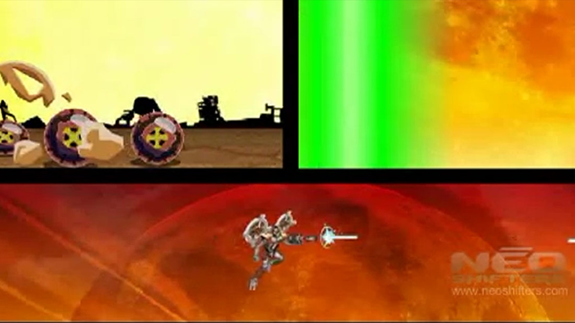
This project is part of my early professional work, created during my time at a company where I had limited production access and tools. It represents an early exploration into real-time animation workflows using Adobe Flash, built under production constraints that required fast iteration and lightweight asset handling. The animation was…

Robots in the Warehouse
UNITY
Robots in the Warehouse
Jul 27, 2025 Simulation

Robots in the Warehouse is a real-time warehouse automation demonstration showcasing autonomous mobile robots operating within a modern distribution center. Designed as a technical showcase, the project focuses on building a scalable industrial environment where multiple robots navigate the warehouse using Unity's NavMesh system, avoid…

Talia
UNITY
Talia
Dec 11, 2022 Visualization

This project explores high-end product visualization using Unity HDRP, showcasing how real-time rendering can achieve the level of quality traditionally associated with offline rendering. Working from a chair model provided by Unity Technologies, I developed the surrounding environment, authored custom materials, created shaders, and…

HDRP Ocean & Volumetric Clouds Showcase
UNITY
HDRP Ocean & Volumetric Clouds Showcase
Aug 24, 2024 Environment

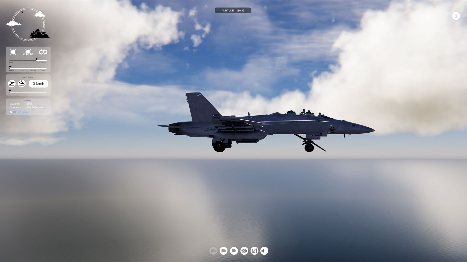
This HDRP showcase was created for a Unity workshop I delivered at Boeing, demonstrating the visual fidelity possible with Unity's HDRP water system, volumetric clouds, and atmospheric lighting. The goal was to build a real-time scene that highlighted realistic ocean rendering, dynamic skies, cinematic lighting, and large-scale…

HDRP Path Tracing Studio
UNITY
HDRP Path Tracing Studio
Jul 17, 2023 Rendering

This project was built in Unity HDRP to showcase high-end automotive visualization using path tracing, custom shaders, lighting, and material development. The scene was designed as a rendering-focused demo where the car could be viewed under different lighting conditions, color configurations, material setups, and studio-style…

Skidloader HDRP
UNITY
Skidloader HDRP
Jun 6, 2022 Rendering

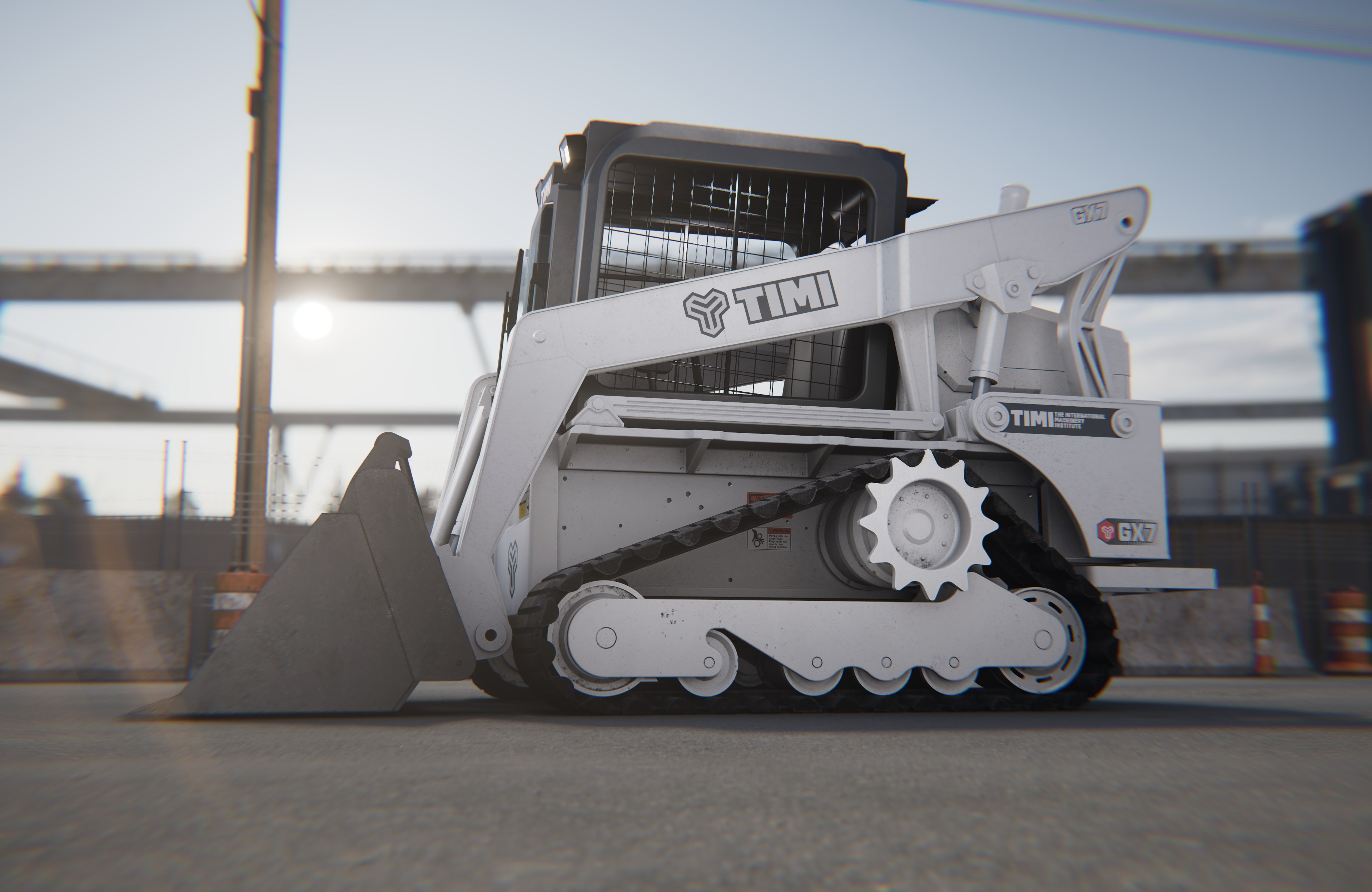
This flagship HDRP project was one of my first major projects at Unity. Unity provided the skid loader model, while Shadow and Light Studios in Paris developed the materials and shaders specifically for the vehicle. My role was to create the surrounding environment, establish the visual direction, and build the complete real-time…

High-Fidelity Unlit Car Paint
Shader Graph
High-Fidelity Unlit Car Paint
Jul 10, 2026 Shaders

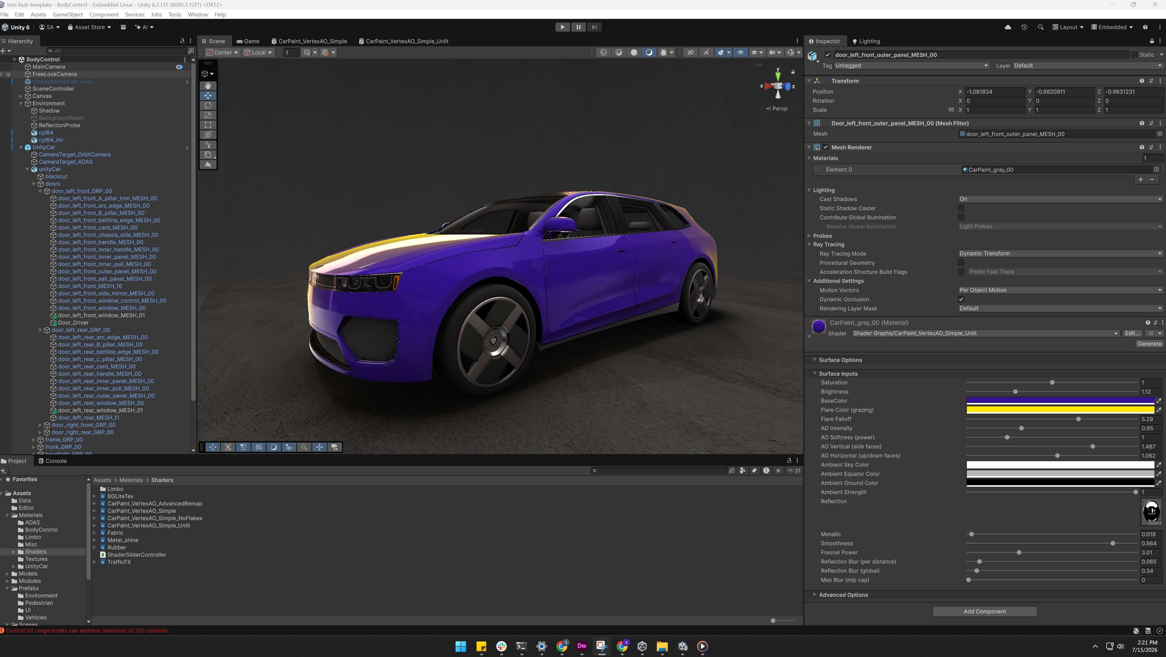
This R&D project explores how a high-fidelity URP Lit car-paint material can be rebuilt as a lightweight custom Unlit shader for performance-sensitive hardware. I retained the visual features that define the original material — body colour, baked vertex AO, a colour-shifting Fresnel flare, environmental reflections, smoothness, metallic…

Airflow Shader
Shader Graph
Airflow Shader
Jul 23, 2026 Shaders

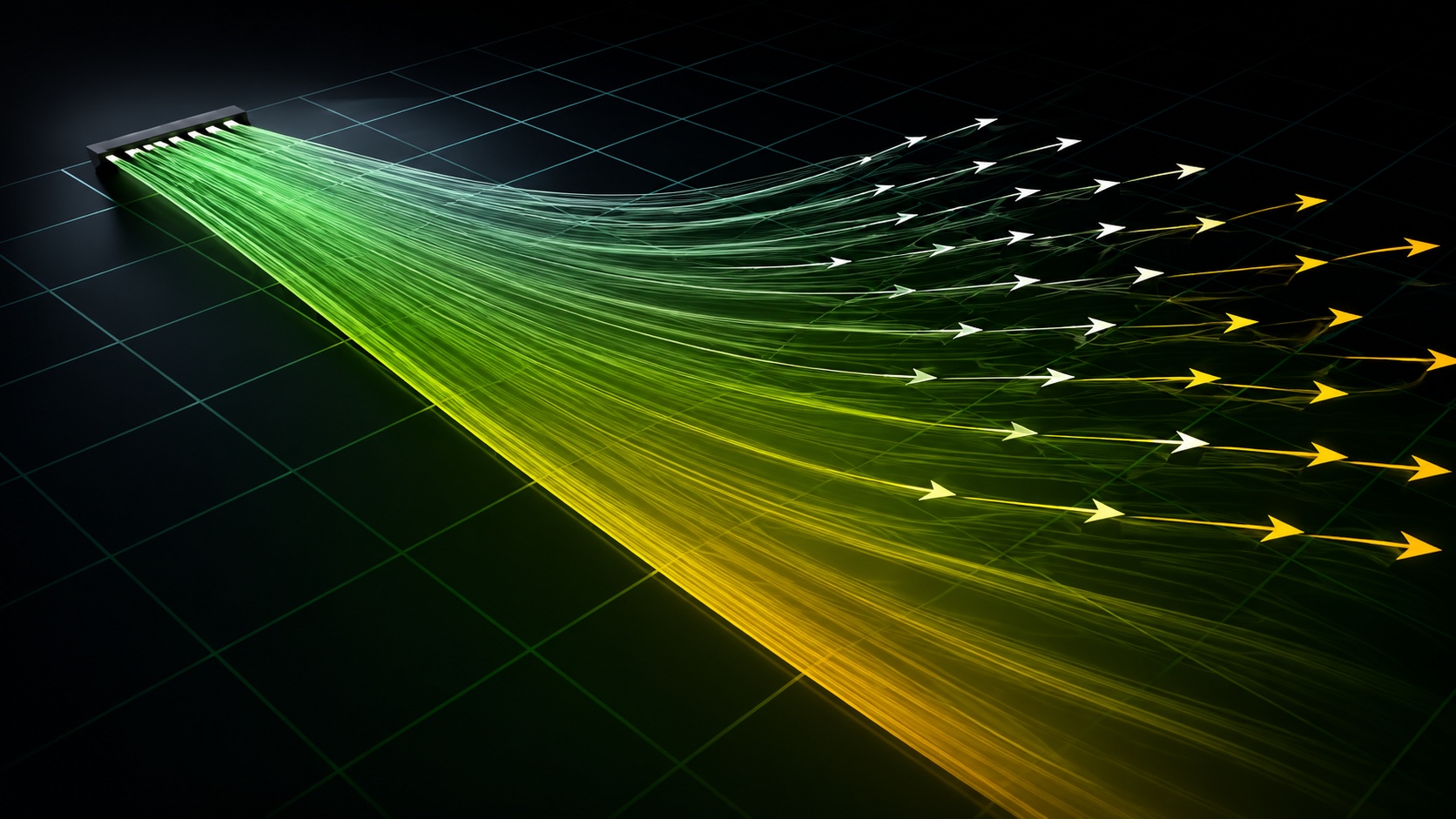
This lightweight airflow effect uses vertex colors as control masks on a simple mesh. Darker areas remain anchored near the vent, while the greener regions allow progressively more movement, making it possible to redirect the airflow without shifting the entire mesh. The shader combines three systems: adjustable directional bending…

SurfaceForge
Shader Graph
SurfaceForge
Jul 24, 2026 Shaders

SurfaceForge is a custom Unity shader inspired by the layered material workflow found in Substance Painter. It allows artists to build and modify detailed surfaces directly inside Unity without creating a separate texture set for every material variation. The shader provides independent controls for base colour, normal, smoothness…

TissueSim
Real-Time Simulation
TissueSim
Oct 5, 2026 Real-Time Simulation

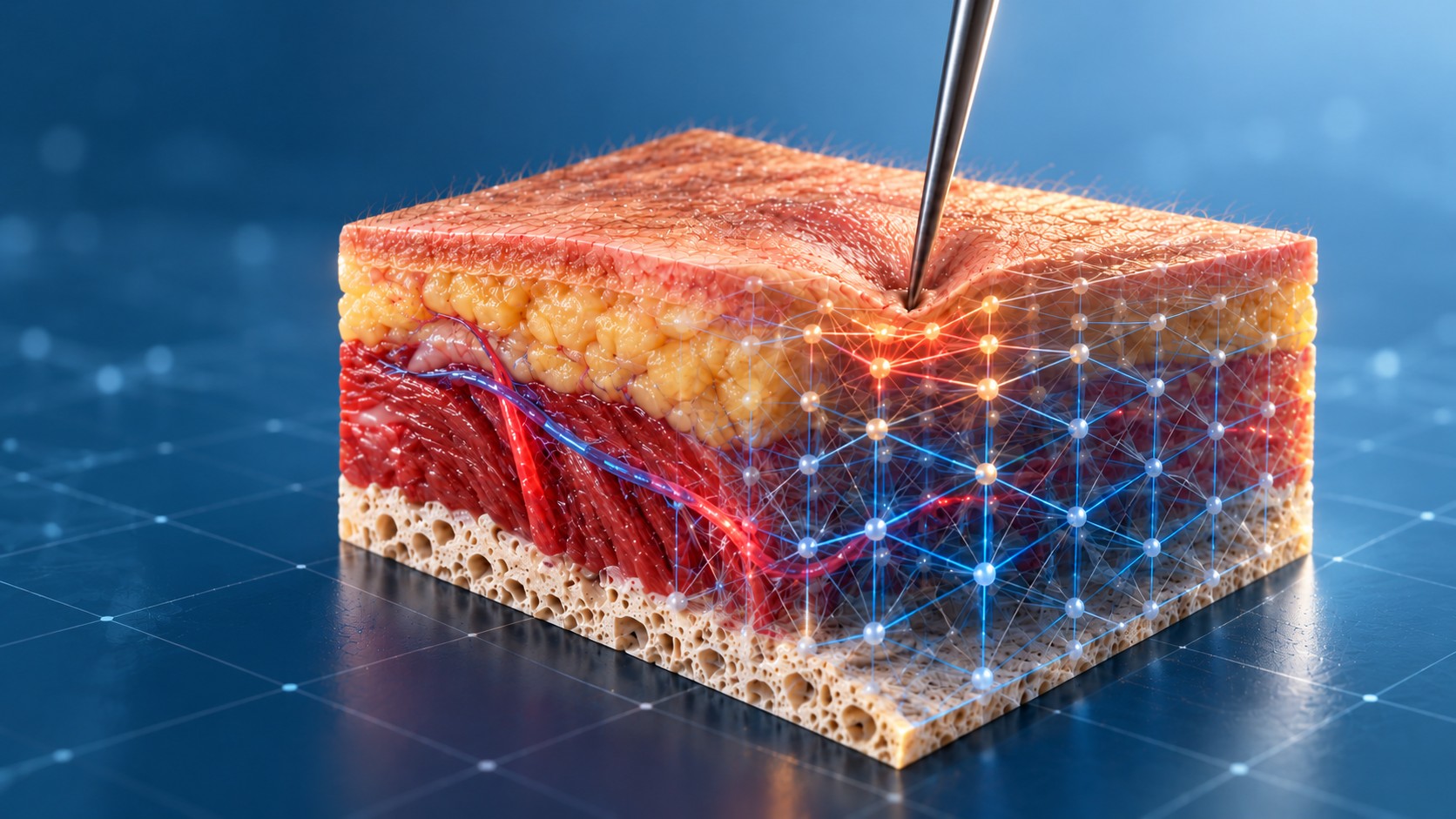
TissueSim is a real-time soft-tissue simulation and visualization system built entirely in Unity. The project explores how deformable tissue, anatomical structure, needle interaction, and procedural rendering can be combined into a single coherent system without relying on external soft-body or medical simulation middleware. At the core…

The Mosaic
+ Featured Work / CINEMA

Minion Mayhem

This project was a stylized CG animation created as part of a licensed Mega Bloks campaign featuring the Minions universe in collaboration with Mattel and Illumination. The goal…

+ Featured Work / CINEMA

TMNT 80s Blockfied

This project was a stylized CG animation inspired by the classic 80s Turtles theme intro, created using Mega Bloks toy-based characters and environments. The goal was to recreate…

+ Featured Work / UNITY

Robots in the Warehouse

Robots in the Warehouse is a real-time warehouse automation demonstration showcasing autonomous mobile robots operating within a modern distribution center. Designed as a…

+ Featured Work / UNITY

Talia

This project explores high-end product visualization using Unity HDRP, showcasing how real-time rendering can achieve the level of quality traditionally associated with offline…

+ Featured Work / UNITY

Skidloader HDRP

This flagship HDRP project was one of my first major projects at Unity. Unity provided the skid loader model, while Shadow and Light Studios in Paris developed the materials and…

Real-Time Simulation

TissueSim

A real-time soft-tissue simulation system for Unity combining XPBD deformation, anatomical tissue layers, needle interaction, procedural cross-sections, bleeding, capillaries, and surface detail.

About the Project

TissueSim is a real-time soft-tissue simulation and visualization system built entirely in Unity. The project explores how deformable tissue, anatomical structure, needle interaction, and procedural rendering can be combined into a single coherent system without relying on external soft-body or medical simulation middleware.

At the core of the project is a volumetric XPBD soft-body solver. The visible tissue mesh is attached to an underlying lattice of particles and constraints, allowing the surface to deform in response to needle contact while retaining the fine detail of the original mesh. Skin, fat, muscle, and bone are defined separately through anatomical depth profiles, allowing different body regions to use different tissue thicknesses and mechanical properties.

The same anatomical data is shared across the simulation, rendering, and interaction systems. Tissue depth determines material boundaries, particle classification, needle resistance, puncture behavior, bone contact, cross-sectional rendering, and the information displayed in the interface. This keeps the visual and physical representation synchronized as the tissue deforms.

The rendering system extends beyond deformation. TissueSim includes a shader-based cross-section system, procedural internal bleeding, surface bruising and blood accumulation, a volumetric capillary network, dynamically generated hair and follicles, and runtime visualization tools for inspecting the solver and tissue state. These systems use the same rest-space tissue information, allowing visual effects to remain attached to the tissue as it moves and deforms.

Project Highlights

  • Category Real-Time Simulation
  • Year 2026
  • Type Soft-Body Simulation R&D
  • Role Technical Art, Simulation & Rendering
  • Pipeline Unity 6, C#, Jobs/Burst, XPBD, URP, HLSL, Claude
  • Download High Fidelity URP Build · 77 MB ↓

Technical Breakdown

How TissueSim Was Built

TissueSim was built as a collection of connected systems rather than one monolithic simulation. The physics, anatomical layers, rendering, needle interaction, bleeding, vascular response, hair, and debug tools all reference the same underlying tissue state so they remain synchronized as the model deforms.

01 — XPBD Soft-Body Solver

The tissue volume is voxelized into a regular 3D lattice of cubic cells. A ray-parity test decides which cells lie inside the mesh, and a particle is placed at every corner of a solid cell, with its mass taken from the tissue's density and the cell's volume. At the resolution used here the 162 mm block becomes 1,440 cells of 6.75 mm, holding roughly 2,000 particles.

Every cell contributes two kinds of constraint. Distance constraints connect all 28 pairs of its corners, covering the edges, the face diagonals, and the body diagonals, so the lattice resists shear as well as stretch; tetrahedral volume constraints split each cell into five tetrahedra that keep the tissue from collapsing. Together that is around 21,000 distance constraints and 7,200 tetrahedra.

An XPBD solver updates the particles every physics step in several substeps: integrate, solve distance and volume constraints, resolve the needle's contact, then derive velocities from the corrected positions. Compliance is set per tissue, so skin is stiff, fat soft, and muscle in between, and links that cross a boundary take the average of the two layers. Bone is not simulated as very stiff tissue; its particles are simply pinned. A critically damped spring pulls the tissue back toward its rest shape, so it recovers after the needle leaves without bouncing.

The visible high-resolution mesh is never simulated directly. Each vertex is bound once to the eight corners of its cell with trilinear weights and moved by their displacement, so the full detail of the original mesh follows the coarse lattice. The whole step runs as a single Burst-compiled job, which brought it from about 57 ms per frame down to around 10 ms on the CPU.

02 — Anatomical Depth Profiles

The anatomical layers are defined by depth rather than painted directly onto the mesh. Each body region stores thickness values for skin, fat, muscle, and bone, and those values become depth bands measured downward from the top surface of the tissue block. The simulator currently loads four injection sites, each with its own profile: the deltoid, the thigh, the calf, and the glute.

Each lattice particle is classified according to its rest position inside those bands, and that classification sets its mechanical behaviour. The same boundaries are used by the needle's force model, the tissue shader, the depth bar in the HUD, and the cross-section, so the physical and visual tissue always agree on where one layer ends and the next begins.

Choosing a new site resizes the block to that region's total depth: the bottom stays on the floor and the top rises or falls, while the textures are projected in real-world units, so a deeper block shows more tissue rather than stretched tissue. The change eases over 0.8 seconds, with the block height, layer boundaries, blend widths, and depth bar all moving together, and the simulation is rebuilt once at the end. Blend widths are capped against each layer's thickness, so a thin layer, such as the 6 mm of fat over the calf, keeps a clean transition instead of being blurred away.

03 — Shader-Based Cross-Section

The cross-section does not physically cut the mesh. A movable clipping plane removes the geometry in front of the slice, and it can stay fixed in the block, follow the camera, or be placed at the needle. Behind the plane, a stencil pass counts the tissue's surfaces from both sides; wherever the count is not zero, that part of the plane lies inside the closed volume and receives a cap, while empty space around the block is left open.

For every visible cut-face pixel, the shader maps the deformed point back to its undeformed rest position. The lattice's current displacement is uploaded each frame as a small 3D texture, and the shader inverts it with a few fixed-point iterations, landing well within a millimetre of the true rest point. That position decides the anatomical layer and generates UV coordinates for the correct material, so the layer lines on the cut face bend around the needle exactly as the tissue does.

The cap writes real depth, so ambient occlusion and shadows treat the cut as a solid surface, and a soft rim shadow along the edge of the cut grounds it visually. As the cut moves deeper, each layer's texture scrolls and ripples slightly, so sliding the plane reads as moving through the tissue rather than across a static picture. All of this produces a cross-section that follows the deformation without creating any new geometry.

04 — Internal Bleeding

The bleeding system starts by recording the needle entry point and the deepest position reached by the tip. Together they define a wound track through the tissue, stored in rest space so it travels with the tissue as it deforms. Each new puncture starts a fresh track with its own random seed, so no two wounds look the same.

Each cut-face pixel measures its distance to that track. The track is not a clean tube: its path is warped by noise, its width swells and pinches along its length, and pockets open where the noise allows. From that distance field the shader builds redness, liquid blood, pockets, mottling, specks, clots, and density blotches, and a soaking front spreads outward over several seconds with fingered edges and a darker tide line.

The response varies according to tissue type. Fat opens widely and stains the most, muscle bleeds tighter and darker with streaks that follow the direction of its fibres, skin stays close to the track, and bone takes no liquid blood at all. Blood appears over time: the core forms within half a second, redness spreads over a few seconds, and after the needle is withdrawn the track partly closes, lingers, and fades.

The final result is composited over the underlying tissue material rather than replacing it. Thin blood stays see-through, so the tissue texture shows beneath it, while thick blood turns opaque with darker clots. The blood is deliberately matte, because a glossy finish produced a long glare streak along the track that read as artificial.

05 — Surface Blood and Bruising

The blood visible on the exterior combines geometry and shader effects. The main blood bead at the puncture is a small procedural mesh, a ring that hugs the needle shaft with a drop running down one side. Every frame it re-reads the deformed skin beneath it, moving and tilting each vertex to follow the surface, and it locates where the shaft actually crosses the skin, which matters when the needle enters at an angle.

No two punctures look the same. The drop's direction, size, amount of blood, and growth speed are randomized per puncture, and the bead swells in over about a second and a half, jiggling slightly when the needle moves. When the needle is withdrawn, the ring closes over the hole, lingers for a few seconds, and then shrinks back into it, while the part of the shaft that was inside the tissue carries streaked droplets of blood.

The surrounding redness, bruising, compression ring, wet film, and blood in the creases are created directly in the tissue shader. The redness stretches into an irregular oval in a random direction, the bruise shades toward a purple-red, and a faint pale ring marks where the needle pressed the skin. The skin height map is treated like terrain flooded to a water level that drops away from the puncture, so blood naturally settles into the lower grooves and pools there with a flat, glossy surface and a thin highlight along its edge.

06 — Procedural Capillary Network

The capillary system is generated procedurally in the shader using a 3D Voronoi field evaluated in tissue rest space. The boundaries between neighbouring cells become vessel paths, creating a true volumetric network rather than a flat painted texture, and it stays fixed in the tissue as it deforms. Two layers of domain warping bend the cell walls into wandering, organic paths, and vessels fade out along their length so the network has open ends rather than closed cells.

Three sizes of vessel are layered together, from larger trunks to fine capillaries, with vertical connectors linking them through the depth of the tissue. The network changes according to tissue type: skin uses finer vessels, fat follows larger lobule-like patterns, muscle vessels are stretched along the fibre direction, and bone contains no vascular network. Each vessel has a soft flush around it that varies between pink and warm orange, along with a mix of venous and arterial colouring.

Additional samples are taken behind the cut surface, at about 1 and 3 mm, to create blurred, translucent vessel layers, giving the impression that some capillaries are embedded deeper inside the tissue. A fluorescent view dims the tissue and makes the whole network glow, as under a fluorescence microscope, which makes its structure easy to read.

07 — Needle-Driven Vessel Response

As the needle advances, the CPU grows a branching influence field along the wound track. Root clusters are seeded every millimetre and a half along the track, and from each one a handful of legs grow outward, wandering, branching, and tapering as they go, with lengths that are mostly short but occasionally reach far. These branches are never rendered directly.

Instead, they are painted into a compact 3D map, storing for each point how strongly it has been reached and when. The map uses cells of about a millimetre, grows if the branches outreach it, and is uploaded to the GPU at most ten times a second.

The shader uses that map to determine which parts of the existing procedural capillary network have been reached by the wound, with a single lookup per pixel. Only real vessels inside a branch's reach fill with blood, and they fill over a moment rather than instantly, so the response feels connected to the vascular structure instead of drawing arbitrary red lines around the needle. The response also follows the tip: it is limited to the tip's current depth, and when the needle is pulled back, the vessels behind it settle gradually rather than all at once.

08 — Procedural Hair, Follicles, and Pores

Hair roots are planted directly onto skin triangles and stored using barycentric coordinates, allowing them to remain attached as the surface deforms. About 8,000 hairs cover the block, and each strand receives procedural properties such as length, width, curl, lean, clumping, and variation, along with a share of coarser hairs.

The hair is groomed rather than scattered: a flow field swirls the strands' direction, clumps pull nearby hairs together, and a parting line divides them, all generated from a single seed so the grooming can be changed in one place. Near the needle, hairs part away from the shaft rather than passing through it.

Every frame, the CPU updates the strand centerlines from the deformed skin. The shader then expands those centerlines into thin camera-facing ribbons, producing visible hairs without cylindrical geometry or hair cards, and the hair casts shadows onto the skin.

Separate shaders render follicles beneath the skin and pores at the surface. Follicles appear on the cut face and the side walls, with a darker bulb at the root, and pores are drawn as small openings slightly elongated in the direction of the hair.

09 — Runtime Debug and Visualization

A dedicated visualization system exposes the internal state of the simulation during runtime. The lattice view can display particles, structural links, voxels, strain, displacement, tissue classification, broken links, and the region currently affected by the needle, and it can be sliced along any axis to see inside the volume.

Additional views show anatomical layers, the active tissue around the needle tip, the full capillary network, and which vessels have been reached or affected. A live panel reports frame time, particle and constraint counts, and cell size, and the simulation's fidelity can be changed while it runs, including rebuilding the lattice at a different resolution.

These modes only visualize simulation data and do not alter the physics, so they can stay on while the needle is in use. They are reached through the same in-app interface as the needle controls, which made them practical for tuning and for explaining the system to others.

10 — Layer Edge Blending and Parallax

The four tissue layers are drawn with a single custom shader rather than four separate materials, so the edges between them can blend instead of meeting at a hard, straight seam. For every pixel, the shader takes the point's depth below the top surface in rest space, finds the nearest layer boundary, and blends the two layers on either side of it across a narrow band, a fraction of a millimetre to a little over one millimetre wide depending on the boundary.

Each layer's height map pushes that boundary locally, so whichever surface is higher at a given point wins: fat lobules bulge into the muscle and muscle fibres break up the edge of the fat, the way real tissue interlocks. Two octaves of low-frequency noise keep the seam from running perfectly level, and a sharpening curve keeps the blend crisp rather than muddy. The band's width is set per body site from the same anatomical depth profile the solver uses.

Parallax then gives that blended surface real depth. The shader ray-marches each layer's height map from the camera's viewing angle, so fat lobules, muscle fibres, and the pores of the bone appear raised and recessed and shift correctly as the camera moves. At a layer edge, the ray marches over the same blended height field that the colours use, and the boundary is re-evaluated at the point the ray lands, so the relief hands over from one tissue to the next exactly where the colour does.

Each layer has its own parallax depth, step count, and an outward setting that decides whether its relief is carved into the surface or raised above it, which keeps the march of a thin layer inside that layer. Fewer steps are used when looking straight down, the slope is capped at grazing angles to avoid stretched streaks, and the depth of the hit is passed to ambient occlusion so the relief is shaded as well. Because everything is evaluated in rest space, the blended edges and their depth stay attached to the tissue as it deforms under the needle.

11 — Per-Side Material Variation

The tissue textures are projected onto the block from each side. Opposite faces project the same stretch of rest space, so turning the block around revealed the same features of the texture on every side, which made the tissue look tiled.

To break that up, the shader identifies which face a pixel belongs to and gives fat, muscle, and bone their own offset, tiling, rotation, and parallax depth on each of the front, back, left, right, and bottom faces, on top of what their materials already define. Tiling can be mirrored and rotation runs a full half-turn either way. Skin and the top surface stay exactly as authored. When a side is rotated, the normal map is turned back by the same amount, and flipped when the tiling is mirrored, so the lighting still comes from the right direction.

The face is identified once per pixel and the result is reused, because the height lookups run inside the parallax ray march, where a per-lookup calculation becomes expensive very quickly; with the work done up front, each lookup in the march costs only a select and a multiply-add. All of it is exposed on a single component in the Inspector, alongside each layer's parallax depth, ray-march steps, and outward offset, with an option to shuffle the side offsets, so the look of every side can be tuned live without editing the shader.

The Core Principle

The core design principle behind TissueSim was to keep every system connected to the same tissue representation. The lattice controls deformation, the depth profiles define anatomy, rest-space coordinates keep visual effects attached to the tissue, and the needle interacts with those same layers. This allows the physics, rendering, bleeding, capillaries, hair, and visualization tools to behave as one coherent system instead of a collection of unrelated effects.

Pipeline & Workflow

  1. A volumetric XPBD soft-body solver: a lattice of particles and constraints under the tissue, run with Jobs and Burst
  2. The detailed render mesh bound to the lattice, so it deforms under the needle without losing its fine surface detail
  3. Skin, fat, muscle and bone from anatomical depth profiles, shared by the solver, the needle, the shaders and the interface
  4. Needle interaction: resistance per layer, puncture, bone contact and withdrawal
  5. Shader-based cross-section, internal bleeding, bruising and blood accumulation, a volumetric capillary network, hair and follicles
  6. Runtime visualization tools for inspecting the solver and the tissue state

Tools & Technologies

Unity 6
C#
Jobs/Burst
XPBD
URP
HLSL
Cl

Credits & Collaborators

Acknowledging the teams, studios, and collaborators behind the project.

Sheraz Asghar
Technical Art, Simulation & Rendering
The XPBD soft-tissue solver and needle interaction, the anatomical depth profiles, the cross-section, bleeding, capillary and hair rendering, and the runtime visualization tools.
Unity Technologies
Engine
Unity 6, the Universal Render Pipeline, and the Jobs system and Burst compiler. Unity is a trademark of Unity Technologies.
Miles Macklin, Matthias Müller & Nuttapong Chentanez
XPBD Method
The soft-body solver is built on Extended Position-Based Dynamics, from their paper "XPBD: Position-Based Simulation of Compliant Constrained Dynamics" (NVIDIA, 2016), which extends Position-Based Dynamics by Matthias Müller et al.